Shandong Gold Lead Machinery Co., Ltd.

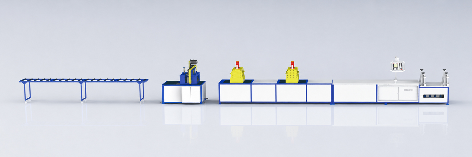
Door and Window Profile Pultrusion Line Layout: From Die to Cutoff
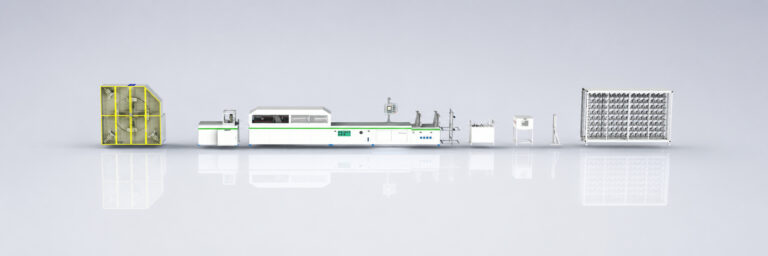
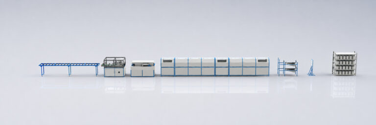
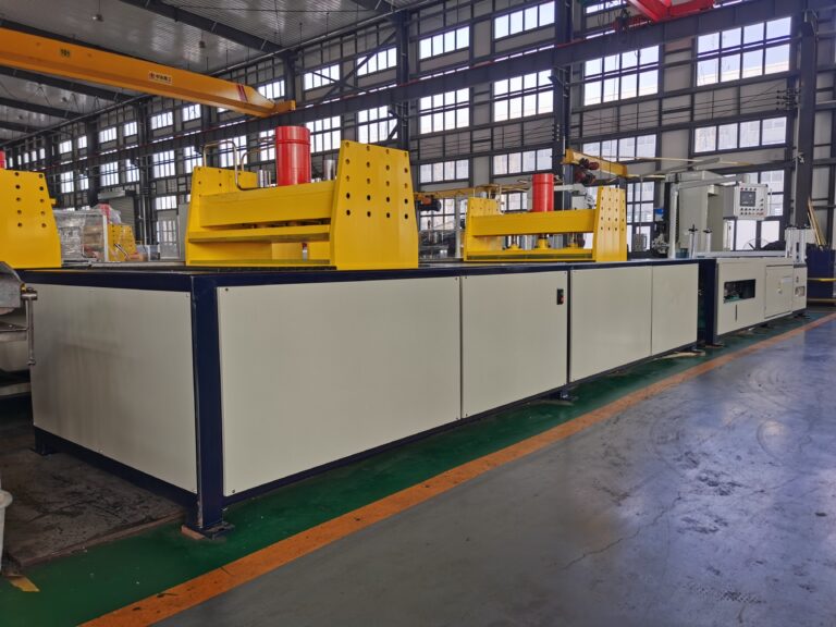
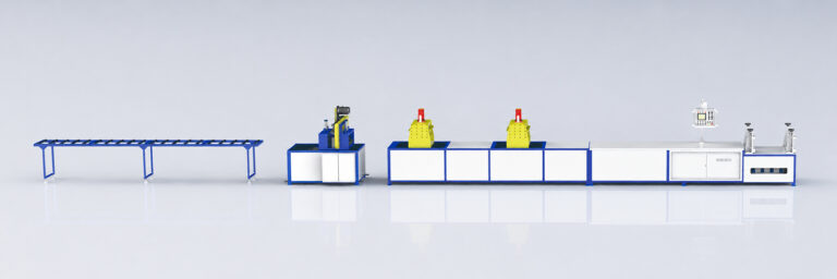
Door and window profile line layouts need to connect tooling, traction, cutting and collection around the actual section range. The finished profiles may have delicate features or appearance-critical surfaces that affect support and handling.
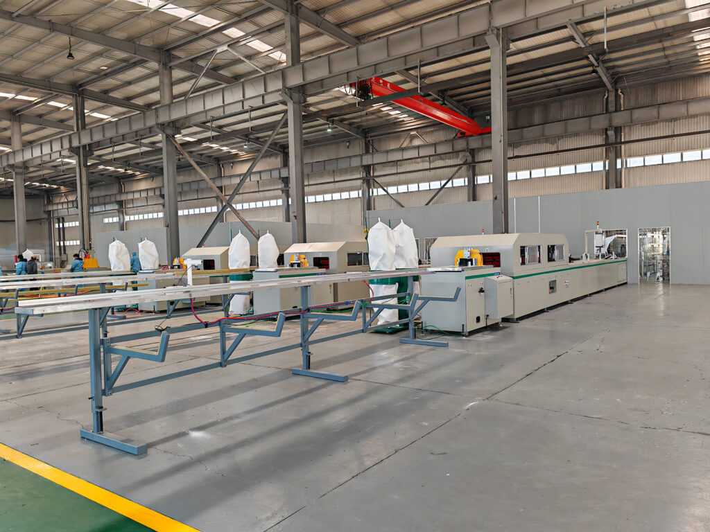
Map the profile through the downstream line
Show the die exit, pulling contacts, intermediate supports, cutoff and collection route. Identify the longest planned product and any secondary machining or assembly handoff. Review how the section is supported without damaging lips, cavities or visible faces. Include start-up material and rejected lengths so their removal does not conflict with normal product handling.
Plan changes between sections
Identify tooling, contact parts, supports and cutting arrangements that change with each product. Provide space for removal, storage and safe installation of those components. Mark alignment references and the inspection point for first-off parts. Do not assume that a line producing one window profile can change to every related door section without additional parts or validation.
A practical decision example
A long door profile with a projecting lip may need a support arrangement different from a simpler window section. Show both in the layout review. Product handling should preserve critical features from die exit through cutting and collection.
Key checks
- Use representative section and length drawings
- Protect critical surfaces through handling
- Map profile-specific changeover components
Next step
A practical layout supports both the machine sequence and the people working around it. Review it using a complete production and changeover walkthrough before final approval.
Review the door and window profile production-line information and share your product specification for a configuration and scope discussion.